@swanktango - I just got my mosfet and am going through the exact same confusion. Did you ever get this resolved?
I’m going to try sketching up some diagrams later and searching the web deeper for help - but the main confusion I’m seeing right now is:
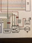
1) everything I’m seeing so far about the MOSFET says to wire it directly to the battery (but right now I’m assuming this is incorrect and it should be wired into the white/red wire from the solenoid/starter relay)
1) EDITED ANSWERED - just wire it directly to the battery (pos & neg) just to minimize resistance points, via https://cx500forum.com/forum/technical-help-forum/34912-wiring-shindengen-mosfet-fh020aa.html
and have the starter relay also going directly to the battery
2) if it’s getting wired from the starter relay does that mean to add the included 30 amp fuse here (in the white/red wire) and keep the existing 20 amp fuse too (which is in the red wire going to the ignition switch)
2) EDITED - having the MOSFET going directly to the battery I'm assuming I should add the 30 amp fuse as directly by the MOSFET diagrams, while also keeping the Main 20 amp fuse where it is correct?
3) THE MAIN CONFUSION - the existing regulator has a “power out” wire (black) and the MOSFET does not, where this get tapped into from?
3) EDITED - after reading CXPHREAK about this black wire being a "Sense wire" that would just completely confuse me - because following this black wire throughout the original cx wiring diagram it must be a power out wire.. right?
3) EDITED AGAIN.. after doing some digging found that the black wire coming from the OEM RR on the 78-81 CX500 serves a different function then on the 82 + CX500 and on the 81 + GLs.. This could be part of the confusion in regards to the black wire being a "Sense Wire". My bike is a 79 cx500 and the black wire from the OEM RR is going to the Rear brake light switch / Horn / Turn Signal Relay.. etc.. so I need to figure out how to safely feed this power.
3) EDITED AGAIN AGAIN... So after looking at the wiring diagram more it appears the "power out" wire (black) I was referring to gets connected to power when the Key is turn On - which would in fact make sense that this is a sensing wire, and that the RR isn't sending the power to my "Rear brake light switch / Horn / Turn Signal Relay.. etc.." its sensing the power at the end of the circuit. Is this correct?
EDITED ps My apologies for ever doubting you CXPHREAK XD - and for not better understanding how a RR works - still learning
My apologies if this has been answered already - I’ll be doing more digging and if I find a clear solution update my wiring diagram and post it.