Honda CX 500 Forum banner

Canadian CX500 Cafe Racer Conversion

462K views 996 replies 87 participants last post by  2ndCXowner  
#1 · (Edited)
Hello everyone,

As with many members on here, I figure I should document my (slow) cafe racer build and maybe get your guys opinion along the way on a few things. I love getting inspiration from others builds and a lot of the things that I do to my bike come from other great members out there.

First a little back story: For as long as I can remember I've always wanted a motorcycle, but never had the money to get one. Last year I was searching the web when this 1980 cx500 custom caught my eye. What a cool looking bike I thought. Long story short I went and picked up my first ever bike and I was so happy. Got it for $250, and knew I had lots to do, starting off with replacing the stator. (Also the PO did not have the ownership and it was an american bike....that took a while to get worked out lol) Fixed it up and it ran great after a little tuning. At that point in time i just wanted to have a bike to ride so I didn't do much to make it look pretty, but now that i have a bit of extra cash (I don't really lol) I want to get it running better and looking fantastic.


Index

Page 1: Background, front fork rebuild, front fender chop, clip-on handlebars, new exhaust wrap and mufflers, new headlight and front signals.
Page 2: New engine new temperature gauge.
Page 3: Painted engine tags and clutch cover.
Page 4: New temperature sending unit.
Page 5: Radiator guard design.
Page 6: Engine paint prep, gauge design and radiator guard fabrication.
Page 7: Dummy lights and gauge redesign
Page 8: Muffler repacking, new tachometer and speedometer, engine painting, engine guards and shock painting, frame touch-up and engine mounting.
Page 9: E-fan mounting and wiring.
Page 10: Redesigned e-fan mounting and steering limits.
Page 11: Gauge and dummy lights wiring and gauge mounting brackets fabrication.
Page 12: Gauge brackets redesign and fabrication.
Page 13: Gauge brackets painting, dummy lights mounting, gauge mounting, lights testing and carb cleaning.
Page 14: Bike startup and oil leak.
Page 15: Cylinder cover painting and test drive.
Page 17: Rim tape installation.
Page 18: Bike drawing start, LED strip testing and tank designs.
Page 19: Rear fender and licence plate holder design.
Page 20: Tank designs, rear fender redesign, bike disassembly and tire hugger design.
Page 21: Tire hugger design and brake light switch bracket fabrication.
Page 22: Battery box design and fabrication.
Page 23: Battery box fabrication and painting and rear fender support tubes fabrication.
Page 25: Rear fender support tubes and rear fender fabrication.
Page 26: Rear fender fabrication.
Page 27: Rear fender mounting bracket fabrication and start of rear fender assembly.
Page 28: Rear fender assembly, test fit and more fabrication.
Page 29: Licence plate bracket design and fabrication, final rear fender assembly, turn signal testing/concept and rear frame modifications.
Page 30: More rear light ideas.
Page 31: Rear hoop and signal mounts fabrication.
Page 32: Rear hoop fabrication continued, new shocks and signal test fit.
Page 34: Rear hoop mock-up, shock limiters, rear hoop modification, rear fender mounting bracket clean up, front electronic pan fabrication.
Page 35: Rear electrical pan fabrication, license plate bracket fabrication and rear fender test fit.
Page 36: Licence plate lights, regulator and starter solenoid mounting and wiring and rear tire hugger fabrication.
Page 39: Rear brake pad replacement, rear hub painting, frame clean up and welding in rear hoop.
Page 40: Priming and painting frame.
Page 41: Getting tire hugger and rear fender ready for painting.
Page 42: Rear fender inside coating.
Page 43: Rear fender and license plate painting, new shock spring coating, shock assemble and install and rear fender, tire hugger and turn signal mounting.
Page 45: 12 Volt time delay modules.
Page 46: Wiring and painting of rear tire hugger and electrical pans.
Page 47: Mounting tire hugger and electrical pans and wiring battery and starter solenoid.
Page 48: Cleaning up electronics and wiring rear turn signals.
Page 49: Pod filters.
Page 50: Header breather tubes and front fork stiffness modifications.
Page 51: New LED brake and running light.
Page 52: Brake flasher module.
Page 53: Brake light mounting and electronic testing.
Page 55: Tire choices.
Page 57: Disc lock.
Page 58: Final Tank designs.
Page 60: Seat pan mock up and fabrication.
Page 62: Changing tires and paint supplies.
Page 63: Tank stripping and seat upholstered.
Page 64: Priming gas tank and new ignition switch.
Page 65: Painting gas tank.
Page 67: Wet sanding tank.
Page 68: Fixing tank mistake, building ignition switch, final 2K clear coat on tank and buffing/polishing tank.
Page 69: Bike pictures and tire hugger mounting clarification.
Page 70: More bike pictures.


Anyways, here are some pictures from before:

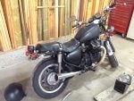
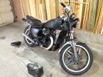
How it looked when I bought it:


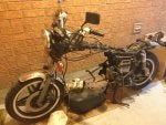
First time taking the engine out:


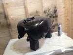
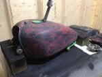
Repainting the tank (temporary):


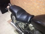
Redone seat cover (temporary):


The bike as it stood last year before any serious mods:

 
#78 ·
So another few pictures:

I picked up a set of Hondaline engine guards from eBay for $10. They weren't in the best of shape, but after sanding them up they didn't look bad at all.


A shot of primer, then gloss black, then a nice matte clear coat:


Next thing to paint: the rear shock covers. They were badly pitted and rusted, so same process: Sand-prime-paint. It's just temporary until I get my new shocks (cause these things suck), but a lack of funds means I won't be getting those for a while lol.


annnnnnnd mounted on the bike (I know, I know...the springs and body are bad)

 
#79 ·
Time to put this silly engine in this frame now.
Rolling out the foot-powered bike felt good. It's been a while since I've seen it.


Before I put the engine back in I wanted to touch up the frame. I had painted it matte black before with a brush and it turned out alright but I wanted gloss black with the spray can this time. Someday when funds are limitless (aka never) I would like to get the frame powder coated, but for now this will do.

Masking off the entire bike (not a fun job):


NOW it's time to put the engine in. Guiding it in with the jack:


And putting the newly painted engine guards on:


The bike as it stood when I went in for the night.


Next thing to work on is getting the e-fan wired up, as well as mounting the new gauges and indicators.
 
#80 ·
Very nice! Love the profile...
 
  • Like
Reactions: Motomicah
#81 ·
Thanks flyinelvis!
I followed your previous build and I must say you have made a beautiful bike! Seeing yours was a big inspiration for me to make my own.
Can't wait to see what's in store for you current build too.
 
  • Like
Reactions: flyinelvis
#82 ·
Just about finished wiring up the e-fan. Next up is the new gauges.
And some pics of the wiring for those who are interested.

Covered the wires coming from the fan with split loom to protect them:


The wires that hook into the fan and temp switch. The red arrow is pointing to the positive lead from the battery, this hooks directly into the fan.
The blue wires are attached to the temp switch and go back to the relay and ground.
One thing I am not certain of is if it matters what lead you attach to on the temp switch as there is no indicator on the actual unit. I am assuming since it's just a switch it does not matter the direction of current flow, but If this is wrong could someone please let me know.


The location of the relay:


To make it a bit more clear, I also took a better picture of the project box that I put all the wiring coming from the old headlight bucket in:


And Lastly how I ended up last night. Got the rad install, all the wiring ran with proper protection for certain areas, and just need to clean up a few loose ends and attach the grounds:

 
#84 ·
No worries, I need all the help I can get lol.
I did think of this and the picture doesn't show it that well but there is a rubber protector all along the edge of the fan so it will not rub on the core. The tabs are bent up slightly also to make sure they don't come into contact either.
The whole fan itself is wired onto the rad at four points with two separate wires for each mounting point. I tried lifting and shaking the whole rad while holding just the fan and it didn't budge an inch.
It's not the prettiest but it's solid. I know a lot of guys weld tabs onto the sides of the rad and mount to that, maybe I should do that instead? What would you recommend?
 
#85 ·
If you really want it to move air, make a plate mount that has some taper to it that will cover the whole radiator and attach the fan to that.
 
#86 · (Edited)
Oh that's really smart! I might look into that. Just for time sake I might keep it the way it is now, and over the winter strengthen the mount like Murray said, and maybe implement the tapered plate idea.
Have you had good results using the tapered plate?
 
#88 ·
That is what the shroud on any mechanical fan is for, to help it pull more air at slower rpms.
If you made a similar arrangement for your Efan then it too will pull more air when it is running.
More air means cooler engine.
 
#90 ·
Yeah I guess that makes sense. It has the small shroud on there but the bigger it is the more air it pulls in like you said. The only thing I need to keep in mind is the clearance but I think I might be able to come up with something.
Do you know of anyone who has done something similar and has pictures, just so I can have something to work off of?

there was a post from a member about rubbing a hole thru his rad core less than 2 weeks ago using a sorry to say better looking mounting system

and no i didnt do it to a bike

but i did have a big block powered chevy truck i used to tow my scarab that i put a tranny cooler on

it had a fan that went on with these neat (i thought ) zip ties that went thru the cooler and the rad to hold everything together

till the hill past orillia on the way into bracebridge on the friday of a long weekend
Well I am not ignorant enough that I will ignore the advice of those who know what they're doing, so the next thing I will do is redesign the mount.
So the main idea is to have the fan mounted off the rad core (say 1/4 inch) and the mounts sturdy enough so that it will not move and hit the core right?
And if I can work in OCR's advice then that should work out great.

Looking back I know I am starting to rush as I want to get a few rides in this season since I've barely ridden at all, but the fact of the matter is, it is much cheaper and faster to spend a couple hours fabricating a proper mount than to have to redo another engine cause this one overheated when the coolant starts spraying from a broken core. I will make sure to take my time now and do things more proper, because what good is a bike that looks good but doesn't run :p

But thanks Murray and OCR for the tips and advice! You guys will probably end up stopping me from hurting myself and I really appreciate that a lot! Make sure to let me know about anything else stupid I do lol :)
 
  • Like
Reactions: zgoldwingman
#89 ·
there was a post from a member about rubbing a hole thru his rad core less than 2 weeks ago using a sorry to say better looking mounting system

and no i didnt do it to a bike

but i did have a big block powered chevy truck i used to tow my scarab that i put a tranny cooler on

it had a fan that went on with these neat (i thought ) zip ties that went thru the cooler and the rad to hold everything together

till the hill past orillia on the way into bracebridge on the friday of a long weekend
 
#91 ·
Okay, finally got a chance to work on the bike last night. First thing to do: Make a stronger mount for the e-fan. I ended up liking exploring/carolina's setup and he was very helpful in sending pictures and details of his setup.
So from what I had lying around I made 3 brackets and attached them to the three mounts on the fan and the 3 mounts for the engine cradle. After positioning and bending the brackets to make sure the fan is in the right place I gave them a quick coat of paint and then mounted them up. So much stronger and cleaner looking! Glad I took your guys advice, and thanks again for the tips! :D

OCR: I didn't have the material with me to make the inner shroud right now, but I won't forget your advice. If I see the temps are higher than normal I will make sure to fabricate something to suck in more air.

Anyways some pictures. The mounted e-fan and brackets:


Tried to get a picture of the gap between the fan and radiator core. It's about 1/4 all the way around, which hopefully should be enough to get the most amount of suction while making sure the fan doesn't hit or rub the core:


And lastly with the rad installed and the guard in place:


Next step: wiring up the gauges and dummy lights (assuming this mount is good enough lol)
 
#97 · (Edited)
Just a small update from last night. Didn't get much time to work on the bike because I went to check out a bike with a friend. I tried to convince him to buy his neighbors CX500 or GL650, but he wanted a sportier bike lol. Ended up looking at a Kawasaki 500 EX which was in good condition and a decent price. I must say, from working on my bike I had a pretty good idea of what to look for, and I think that's pretty cool: the fact that you can learn so much from these builds.

Anyways, all I got finished doing was limiting my handlebar radius (the controls were hitting the tank since I put the clip-ons on).
This idea is not mine at all, I just saw a thread where the person did this yesterday but couldn't find it again today. If the person who came up with this idea reads this, then thank you for the idea and feel free to give yourself credit :D

Drilled, then tapped holes into the stopper thingies (M5 0.8 threads), grabbed two M5 bolts from work and stuck them in there. The heads are about 1/2 inch thick which gave me just enough space between the controls and tank:


EDIT: The user was Greasemonkey247, and the original post can be found here: http://cx500forum.com/forum/general...neral-discussion/27672-barn-fresh-corrosion-cx500-cafe-buffed-4.html#post319714. Thanks again for the Idea!
 
#99 ·
I purchased just one roll from Dime City Cycles. The recommended overlap is about 1/8" (there is a line on the roll showing how much to overlap). I wrapped the first exhaust without cutting the roll just to make sure I had enough to wrap them both evenly, and by having a 1/2" overlap there was not enough material. So I took it off and wrapped it again using the 1/8" overlap all the way and it just barely fit. I used up every last bit of the roll. If you want to wrap anything more than just the headers you will need two rolls, or they sell a 50' roll as well which would give you enough to wrap it twice if you ever needed to. I was cheap so I just bought the cheapest one lol :p
Hope that helps!
 
#101 ·
A little bit of electrical work was done over the weekend, but as usual I didn't get to work a whole lot on the bike.
Checked a few systems and was happy with the results. The e-fan turned on via the relay when I bridged the temp sensor (that thing sounds wicked!) and the temp gauge needle moves (have yet to fully test it yet with the engine running).
Wired up all the gauge lights and dummy lights as well:


Got all the backlights working too (the speedo and tach bulbs are very tiny and don't give off a lot of light. I may look into getting something a bit brighter; maybe an LED bulb. I can read the numbers in the dark, but at the same time they could be a lot better too):


And another picture to show how the screws I bolted in help to stop the controls from hitting the tank (the other side has a bit less clearance):

 
  • Like
Reactions: CliffD
#104 ·
So......after looking at my triple clamp, handlebars and ignition placement I found that both the tach and speedo fit perfectly into the circular gap left where the old gauges mounted from. It also allowed me to use the holes in the triple clamp to mount the bracket which gave a bit stronger mounting point (plus it hides the ugly area where the old handlebars went and saves me from smoothing out the top triple clamp)
So disregarding most of my previous drawings I made lol, I set about making a REALLY rough cardboard template:


Then I made one up and test fitted it making sure it had good clearance and looked alright. Then used the template to make a second one:


What the brackets look like mounted up:


And the gauges mounted. I still have to paint the brackets black and then mount the temp gauge and dummy lights. Hopefully I can get that done tonight:


#106 ·
LOL, no worries I am glad that you are enjoying the build :D It makes it all the better when kind people like you support and enjoy all the effort that goes into making these bikes so amazing :)

Thanks a bunch! I think they turned out pretty good too. Murray was telling me the 90 degree bends might fail from fatigue at some point though, so I have to look into reinforcing those before I mount the temp gauge, especially because I most will most likely be using the mounting points from the gauges to mount the bracket for the temp gauge.
 
#108 ·
Thanks! Lets hope after I mount the temp gauge and dummy lights up there too it still looks as good :p
If not I may figure something else out for the temp gauge because I really like the look of the gauges as they currently lay.
 
#110 ·
I really liked your dash idea! So clean looking and i love how smooth it matches in with the original gauges. What went wrong with the LED's?
I am sure whatever I come up with you will make a thousand times better :p
 
#111 ·
In an attempt to avoid the tach and speedo falling off from a fatigued 90 degree bend (thanks again for the tip Murray) we have come up with some possible solutions to strengthen the bracket a bit.
Option one is to weld a bent 1/4 rod in the middle of the bracket. This would be best as it strengthens the entire bracket too. Only problem is clearance at the top bend so I have to check and see if it'll fit.
Option two is to fabricate side gussets that strengthen the bends. This might be the option I go with at it is a simple fix and won't interfere with the triple clamp.
Option three is to weld a bead along the inside edge of the bend. Probably not the strongest but it may work.

 
#113 · (Edited)
After looking at the bracket, option 1 would not work because there is not enough room at the top. So option two it is. Got some stuff made last night (after a delicious sushi feast :tongue8:) Hopefully I'll start welding them up during lunch today, or tomorrow if I can't get it done. (Or I may get someone else to weld it up cause I still suck at it lol)

Made all the support gussets for the tach and speedo gauge brackets:


And started to make the bracket to hold the dummy lights and temp gauge. Cardboard templates helped a lot in getting the right size and shape:


The pieces all cut out and shaped. Grinding down the top part of the bracket (far right) was less than enjoyable <_< :

 
  • Like
Reactions: CliffD
#114 ·
I was going to wait until I was all done the brackets before I posted the results but it's taking a bit longer then I thought so I figured I would share with you guys a quick update.
I got all the brackets welded (welding thin material is awful <_<) and sanded, then mounted them up for a test fit and still found that it was flexing a bit too much for my liking. The thin vertical part needs to be reinforced so I will be welding a thick bead along the inside face to make it a bit stronger.
And of course, the update wouldn't be complete without some pictures:

All welded up and some rough grinding done. As you can see on the left bracket I started to clean up the inside a bit too using a cut-off disk with a dremel:


After more grinding and sanding and drilling the holes for the dummy lights:


I have circled the area that needs reinforcing. I kind of figured it would though as the side gussets had to be ground down a lot to avoid hitting part of the tripled clamp, thusly exposing the thin vertical section:

 
  • Like
Reactions: CliffD
#116 ·
Thanks Lacher! The LED's are from a place about a minute away from my work called Neutron Electronics. The screenshot below is from their online magazine and are the type of lights I bought. They were around $4 CAD each I think. I looked on eBay but I couldn't find a style I liked, and so I ran into the store and found these. Any large electronics store should have something similar. I believe they are intended for electrical panels, but they will work great for instrument lights as well. The quality is really good, and the lights are diffused a bit so they don't distract or blind you when they're turned on which is really nice, especially in the night time! They also have built in resistors that let them run off of 12V which meant I could just plug them right into the original wiring.

 
#117 ·
I used those and bought them from the same store - but in Hamilton.
I didn't have much success. They would go on when they should be off and I didn't feel confident with them most days.
I am now designing a new dash with integrated LED's in the tach and speedo.

Good luck
 
#118 ·
Aw man really?! That's a bummer. I'll give these a go for now, but I fear I will end up with the same issue as you if it's a common thing. Any ideas which similar kind of lights work well?
I can't wait to see your new dash idea! Keep me posted on how it goes :)