Honda CX 500 Forum banner

Canadian CX500 Cafe Racer Conversion

462K views 996 replies 87 participants last post by  2ndCXowner  
#1 · (Edited)
Hello everyone,

As with many members on here, I figure I should document my (slow) cafe racer build and maybe get your guys opinion along the way on a few things. I love getting inspiration from others builds and a lot of the things that I do to my bike come from other great members out there.

First a little back story: For as long as I can remember I've always wanted a motorcycle, but never had the money to get one. Last year I was searching the web when this 1980 cx500 custom caught my eye. What a cool looking bike I thought. Long story short I went and picked up my first ever bike and I was so happy. Got it for $250, and knew I had lots to do, starting off with replacing the stator. (Also the PO did not have the ownership and it was an american bike....that took a while to get worked out lol) Fixed it up and it ran great after a little tuning. At that point in time i just wanted to have a bike to ride so I didn't do much to make it look pretty, but now that i have a bit of extra cash (I don't really lol) I want to get it running better and looking fantastic.


Index

Page 1: Background, front fork rebuild, front fender chop, clip-on handlebars, new exhaust wrap and mufflers, new headlight and front signals.
Page 2: New engine new temperature gauge.
Page 3: Painted engine tags and clutch cover.
Page 4: New temperature sending unit.
Page 5: Radiator guard design.
Page 6: Engine paint prep, gauge design and radiator guard fabrication.
Page 7: Dummy lights and gauge redesign
Page 8: Muffler repacking, new tachometer and speedometer, engine painting, engine guards and shock painting, frame touch-up and engine mounting.
Page 9: E-fan mounting and wiring.
Page 10: Redesigned e-fan mounting and steering limits.
Page 11: Gauge and dummy lights wiring and gauge mounting brackets fabrication.
Page 12: Gauge brackets redesign and fabrication.
Page 13: Gauge brackets painting, dummy lights mounting, gauge mounting, lights testing and carb cleaning.
Page 14: Bike startup and oil leak.
Page 15: Cylinder cover painting and test drive.
Page 17: Rim tape installation.
Page 18: Bike drawing start, LED strip testing and tank designs.
Page 19: Rear fender and licence plate holder design.
Page 20: Tank designs, rear fender redesign, bike disassembly and tire hugger design.
Page 21: Tire hugger design and brake light switch bracket fabrication.
Page 22: Battery box design and fabrication.
Page 23: Battery box fabrication and painting and rear fender support tubes fabrication.
Page 25: Rear fender support tubes and rear fender fabrication.
Page 26: Rear fender fabrication.
Page 27: Rear fender mounting bracket fabrication and start of rear fender assembly.
Page 28: Rear fender assembly, test fit and more fabrication.
Page 29: Licence plate bracket design and fabrication, final rear fender assembly, turn signal testing/concept and rear frame modifications.
Page 30: More rear light ideas.
Page 31: Rear hoop and signal mounts fabrication.
Page 32: Rear hoop fabrication continued, new shocks and signal test fit.
Page 34: Rear hoop mock-up, shock limiters, rear hoop modification, rear fender mounting bracket clean up, front electronic pan fabrication.
Page 35: Rear electrical pan fabrication, license plate bracket fabrication and rear fender test fit.
Page 36: Licence plate lights, regulator and starter solenoid mounting and wiring and rear tire hugger fabrication.
Page 39: Rear brake pad replacement, rear hub painting, frame clean up and welding in rear hoop.
Page 40: Priming and painting frame.
Page 41: Getting tire hugger and rear fender ready for painting.
Page 42: Rear fender inside coating.
Page 43: Rear fender and license plate painting, new shock spring coating, shock assemble and install and rear fender, tire hugger and turn signal mounting.
Page 45: 12 Volt time delay modules.
Page 46: Wiring and painting of rear tire hugger and electrical pans.
Page 47: Mounting tire hugger and electrical pans and wiring battery and starter solenoid.
Page 48: Cleaning up electronics and wiring rear turn signals.
Page 49: Pod filters.
Page 50: Header breather tubes and front fork stiffness modifications.
Page 51: New LED brake and running light.
Page 52: Brake flasher module.
Page 53: Brake light mounting and electronic testing.
Page 55: Tire choices.
Page 57: Disc lock.
Page 58: Final Tank designs.
Page 60: Seat pan mock up and fabrication.
Page 62: Changing tires and paint supplies.
Page 63: Tank stripping and seat upholstered.
Page 64: Priming gas tank and new ignition switch.
Page 65: Painting gas tank.
Page 67: Wet sanding tank.
Page 68: Fixing tank mistake, building ignition switch, final 2K clear coat on tank and buffing/polishing tank.
Page 69: Bike pictures and tire hugger mounting clarification.
Page 70: More bike pictures.


Anyways, here are some pictures from before:

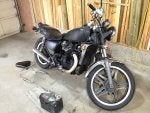
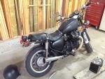
How it looked when I bought it:


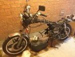
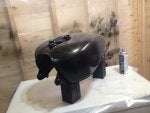
First time taking the engine out:


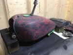
Repainting the tank (temporary):


Redone seat cover (temporary):


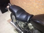
The bike as it stood last year before any serious mods:

 
#36 ·
Pictures would be great ... I'd be very interested in hearing if the sending unit leaks or not and how good you feel it is in reading the actual water temp when you get that engine running ... looks like a decent gauge (better then the stock one) ... and it must use less power then the stock one (I think I remember reading the the stock one can draw up to an amp depending on temp of engine)
 
#37 ·
Got some pictures! I really hope it doesn't leak, but I've heard stories that it might. I made sure to put lots of dope on it though, and when I was threading it in it was a good tight fit so fingers crossed it works.
And it is a very nice gauge. I've seen a few members use it now and they all seem to have good results with it. Pretty sure anything that is stock uses more power than modern tech lol, but if that is true then it should be a very nice upgrade!

Here is the new sending unit threaded into the mount:


The old sending unit (notice how far the end of the unit sticks out):


And since I forgot to take pictures of the new unit out of the box, and I really did not want to take the new unit out of the engine I made a simple picture to illustrate what it looks like in the adapter. The more bronze/copper colored part is the adapter and the darker part is the actual sending unit. You can see what I meant about it not sticking out as far as the stock unit, but hopefully it should still work.

 
  • Like
Reactions: djenkins
#39 ·
No problem :)

Yep, I shall keep you posted for sure. I think it should be fine, and if it's really leaking badly I'll just throw some silicon around it to hopefully solve the problem lol.
I also should have mentioned that the adapter has an aluminum crush ring around it so that should help to stop it from leaking too.

I'm not quite there yet....but it's in the near future haha. Still have to finish putting the engine together, then wire up the e-fan and lastly the gauge. Plus some minor paint touch up here and there on the frame. But I will post pics for sure!
 
#41 ·
Oh that's a great thread!! I like his mounting idea too. Looks like it should all work out then so I'm happy about that. Thanks for the link Greycat :D
 
#43 ·
So while I am sitting here at work trying not to die from boredom I was thinking about the radiator shroud/guard thingy and how I never really liked the stock one. Plus mine is kind of falling apart and whatnot.....soooooo on to making a custom one of those too lol.
I just want something simple I can do with hand tools (seeing as I don't have access to a CNC Mill right now) and came up with this design. I was originally going to do just the holes but it looked kind of bare. So I threw in some text and it looks a bit better. Now the question is....what style and position of text do you guys like the best? I am leaning towards #3 but we shall see.....

 
#45 ·
here is the thing

the stock shroud is designed so it is wider than the rad and scoops air into the rad to help cool it at slow speeds it makes a huge diff

especially on my electric fan bikes like the goldwing or my 650s they dont need to be quite this big but it makes a big diff on hot days
Ooh that's good to know. I guess I could try and make the new one similar...but now I'm thinking it might just be best to stick with the stock one. I think I ran into heat problems with my previous engine, and that's probably part of the reason it seized on me.
So the idea is to have a "scoop" shape so that air is directed into the rad? That makes sense now that I think about it more. Thanks for the tip!
 
#48 ·
Hey Murray, do you think something like this would work? If I mounted two fins on either side of the rad guard angling the air towards the rad. It's similar to what you have in the picture and would be easy to do too.

 
#49 ·
One thing that really sucks about Canada....you can't buy half the things that you can in the states :upset:
Searched everywhere for VHT or duplicolor engine primer.....doesn't exist in Canada.
Searched for certain color of VHT or duplicolor engine paint...doesn't exist in Canada.
Searched for normal prices for a can of spray paint...............doesn't exist in Canada.
So my family is heading to the states today, and I am going to see if they can pick me up a few cans of the stuff I need.

Nearly finished the rad guard thingy, and engine is almost fully cleaned and ready for paint. Just waiting on the temp switch from china for the e-fan and I should be able to start wiring things up.
 
#58 ·
One thing that really sucks about Canada....you can't buy half the things that you can in the states :upset:
+1 to that...

Annoys me especially on Amazon. COM has way more than CA has, and even though the USD/CAD are about the same, the COM site is still much cheaper. :mad:

eBay too... it's as if no one in Canada sells on eBay. :D
 
#51 · (Edited)
I checked at Napa and Canadian Tire and the guy said that there was something in the primer that the Canadian government wouldn't allow and he wouldn't be able to order it for me unfortunately. And the other color I figured I can get it cheaper in the states too rather than ordering it up here. It really is a bummer though, this build would be so much cheaper if it was in the states :(

But....I have just learned that the paint is picked up!! Can't wait to put the engine back in the bike :D
 
#52 ·
So......progress........engine is all back together, cleaned up and masked off. Sprayed the primer on last night and gonna do the actual paint tonight then clear coat Saturday or Sunday.

Radiator guard is made and in the process of painting. I tried to make those side skirt things but hated the final look, so back to the drawing board on that part of them. I really want them though, because like Murray said, they will make a difference....and I don't think it wise to not listen to him lol.

In case you were curious why I needed the certain color of paint from the States see the picture below. I was going to use Duplicolor cast iron paint (on the right) but after I painted the clutch cover I was looking at it I noticed it had a gold/yellow tinge to it which I did not like one bit. Tried looking everywhere else for a similar but non-yellow color and the only one I could find was the VHT cast iron (on the left) which you can not buy in Canada. You can see the difference between the Duplicolor and VHT in the picture, and I am much happier with the VHT!


And the engine all taped up and ready for a shot of primer (You can see where the PO [not Kameron] tried to "polish" the engine with a wire wheel) :

 
#53 ·
When I am not working on my bike all I can think about is working on my bike lol. I bought some new gauges a while back and have been pondering how to mount them along with new dummy lights and the water temp gauge.
So after fooling around with some arrangements I came up with a few ideas for the layout. The mounting bracket with most likely be changed slightly seeing as I am at "work" right now and can't remember the shape of the mounting points. The bottom of it will be formed to fit around whatever is on the bike (ie, ignition, choke, etc...)
Anyways I am curious to see what you guys think. I prefer the temp gauge on the lower position but wanted to see what it looked like above too, although I think it stands out a bit too much.

Right now I am leaning towards #2.

Any comments are appreciated! :D

#1


#2


#3


#4
 
#56 ·
Ignition's pretty big; here's what it looks like with the (same?) gauges:
Oh man it is isn't it....Maybe i can move the ignition elsewhere....but yeah, looks like it's gonna be a tight fit to say the least. Thanks for the pics! It's been so long since I looked at the frame of my bike I had forgotten what it looked like lol.
 
  • Like
Reactions: Misenhei
#57 ·
I like #1. To me it looks more tidy. Almost more jet-fighterish.
Good point! I think if I can fit the temp gauge on the bottom I will go with it. That way all the lights are in one group and not scattered about. Should be easy to clean up the wires too now that I think about it.
Thanks for the feedback!
 
#60 ·
So the radiator guard is finished. I still need to do the wind scoops, but am still figuring that part out. Might run the bike for a bit and see what the temps are like without them, but there is a reason why Mr. Honda designed the stock one the way he did so I think I will be making some in the not-too-distant future.
Anyways....pictures of the build and painting:

After making a rough design and bending it to shape, I marked out 1/2 inch spaced lines on the horizontal and 1/4 inch spaced lines on the vertical. Every row of holes was offset 1/4 and this allowed the holes to be drilled closer together and also made it look a bit neater:


After drilling 300 pilot holes by hand (1/8 inch drill bit I think) and testing the look of the final hole size:


After drilling another 300 holes with the larger 3/8 inch drill bit, and reaming all holes to get rid of burs:


Sanded and flattened out as best I could seeing as drilling all the holes warped the piece a bit (didn't even get it close to perfect lol), and then a quick shot of primer:


Then a shot of red paint along where the logo is to go. To make the stencil I had some black vinyl lying around, so I printed out the logo on paper, used double sided tape to stick it to the vinyl, then cut the logo out using an x-acto knife:


And lastly a coat of black. Then removed the logo stencil and gave it all a nice clear coat to hopefully keep the paint from chipping. The logo came out alright, and the black came out a little textured....but whatever, I don't feel like redoing all that work, so it stays the way it is lol:


Would have been so much easier if I had access to a cnc machine or water jet cutter lol :shame:
 
  • Like
Reactions: djenkins
#62 ·
Also picked up some indicator lights yesterday. They have built in resistors that allow them to run directly off of 12 volts, meaning I can tie them directly into where the stock dummy lights go.
Got them from Neutron Electronics here in Guelph Ontario, but any big electronics stores should have them:

 
#65 ·
So like Misenhei stated I probably won't be able to mount the temp gauge so low without moving the ignition switch. I might be able to do something like this, but I might also just mount the temp gauge elsewhere on the bike (possibly the rad):

 
#67 ·
You make a good point again, I would like to keep it within a glance at all times too. Looks like this shall be the layout then.....assuming my fabrication skills are as good as my art skills lol
 
#68 ·
I can't help but smile as I follow this thread. At first, I thought this may just be a dream...a very cool one for sure, but I didn't think I'd see a conclusion. I must admit, I was wrong and very much look forward to the final product!

Excellent idea and good job working through it :)
 
#70 ·
Thanks so much for the kind words CliffD :D
Yeah it's always been my dream to have a bike, and when I first got this one I thought I would drive it for a bit then sell it to get something a bit nicer, but after seeing some other peoples builds it inspired me to put some effort into making this one look great.
I can't wait to see how it turns out either! (hopefully good lol)
 
#71 ·
Thanks Jester, it has been a great (but long) experience so far and I still can't wait for all the stuff I still get to design and build :)
I am sure you'll probably have yours designed and built before I get this thing done lol
 
#72 · (Edited)
So glancing through old photos of the build I noticed I had forgotten to add the photo of my baffle mod. When I first bought the mufflers I thought they seems pretty loud....and very "poppy". Took the baffles out and sure enough a few strands of "tissue paper" was all that was muffling the sound. So bought some fiberglass sheets (4 stroke stuff from Royal Distributing, but could be found at any bike shop), some steel wool and some 1" hair catchers for a sink. Wrapped up the mufflers with a layer of steel wool and then the fiberglass blanket and cemented the hair catchers in place using muffler crack filler. Put them back on and it made a HUGE difference. Much lower sounding and less "poppy" now. Quite pleased with them now.
P.S. The hair catcher was not my idea, Kameron was the first one that I know of to do the mod, so kudos to him

You can see the hair catchers in place below. Seems to building holding well, but if you had a welder you could just tack it in place and it would be much better probably:


Also got the tach and speedometer in which I purchased from my birthday money. I got the tach here: Mini Universal Motorcycle Mechanical 12K RPM Tach Tachometer Gauge 1 4 | eBay and the speedometer from Partsnmore.com

 
#73 ·
Totally unrelated to the build (well sort of), but I thought I would share my first welding experience. It's good practice for when I modify the rear of the bike by welding on a hoop or something similar.
First thing I learned....it's a lot harder than it looks.
Second thing I learned.....don't put too big a weld or you'll spend hours grinding them down to make them flush :rolleyes:

Anyways here are some pictures....because why not lol.

This was probably one of my best welds....I don't want to show my worst haha:


The one side all welded up:


And what exactly is it? A stand I made for a touch screen at work. It's not the prettiest, nor the straightest....but I am so proud of it lol

 
  • Like
Reactions: CliffD
#74 ·
hmm pretty light duty for a touch screen lol

good job

the worst thing about welding is you really have to practice

it is possible to create a perfect looking weld that has absolutely no penetration or hold

that is why they xray welds tio see if there is voids in them

and bend test a butt weld to test for strength
 
#75 ·
Lol yeah I wasn't sure how strong it would be when designing it as I've only ever worked with bolt together stuff, but I am surprised at how strong a weld actually is.

Yeah even when I ground down my "good" welds there was a few tiny pockets so I can definitely understand that there is an art to welding.
I used to work in a material testing place and performed numerous bend tests, and I saw a lot of failures when the weld looked great.
I don't think I'll ever become a professional, but I feel confident enough to weld little pieces for my bike now....maybe
 
#77 · (Edited)
Alrighty so there has finally been some noticeable progress on the build. I Wish I could work on it more than I do, but family is more important so the build tends to get pushed aside some times haha.
Rather than dump all the pictures on here at once I am going to split it up a bit.

First things first....The heart of the beast. Finally done and ready to put back into the bike. I could've got it done a lot faster probably, but I wanted to take my time and make sure I did everything right. I do not want to have to take this thing out again for a couple years at least lol.

A nice coat of primer:


Then a couple coats of the VHT cast iron and a nice layer or two of clear:


With all the masking off and the black accent parts attached this is the final engine (still have to paint the covers though). Not too bad if I do say so myself, and I am really happy with how the paint came out:


What's that saying? "out with the old, in with the new".....Well I must say...the "new" is a lot better looking and much more mechanically sound than the "old" (to be fair I took off all the good parts from both engines and now the old one looks even worse lol).
I feel like I have learned a lot of what not to do on the old engine though, so hopefully I can keep this one running great!

Bye bye ol friend. You shall be kept for parts though, either for me or someone else.