Honda CX 500 Forum banner

Canadian CX500 Cafe Racer Conversion

462K views 996 replies 87 participants last post by  2ndCXowner  
#1 · (Edited)
Hello everyone,

As with many members on here, I figure I should document my (slow) cafe racer build and maybe get your guys opinion along the way on a few things. I love getting inspiration from others builds and a lot of the things that I do to my bike come from other great members out there.

First a little back story: For as long as I can remember I've always wanted a motorcycle, but never had the money to get one. Last year I was searching the web when this 1980 cx500 custom caught my eye. What a cool looking bike I thought. Long story short I went and picked up my first ever bike and I was so happy. Got it for $250, and knew I had lots to do, starting off with replacing the stator. (Also the PO did not have the ownership and it was an american bike....that took a while to get worked out lol) Fixed it up and it ran great after a little tuning. At that point in time i just wanted to have a bike to ride so I didn't do much to make it look pretty, but now that i have a bit of extra cash (I don't really lol) I want to get it running better and looking fantastic.


Index

Page 1: Background, front fork rebuild, front fender chop, clip-on handlebars, new exhaust wrap and mufflers, new headlight and front signals.
Page 2: New engine new temperature gauge.
Page 3: Painted engine tags and clutch cover.
Page 4: New temperature sending unit.
Page 5: Radiator guard design.
Page 6: Engine paint prep, gauge design and radiator guard fabrication.
Page 7: Dummy lights and gauge redesign
Page 8: Muffler repacking, new tachometer and speedometer, engine painting, engine guards and shock painting, frame touch-up and engine mounting.
Page 9: E-fan mounting and wiring.
Page 10: Redesigned e-fan mounting and steering limits.
Page 11: Gauge and dummy lights wiring and gauge mounting brackets fabrication.
Page 12: Gauge brackets redesign and fabrication.
Page 13: Gauge brackets painting, dummy lights mounting, gauge mounting, lights testing and carb cleaning.
Page 14: Bike startup and oil leak.
Page 15: Cylinder cover painting and test drive.
Page 17: Rim tape installation.
Page 18: Bike drawing start, LED strip testing and tank designs.
Page 19: Rear fender and licence plate holder design.
Page 20: Tank designs, rear fender redesign, bike disassembly and tire hugger design.
Page 21: Tire hugger design and brake light switch bracket fabrication.
Page 22: Battery box design and fabrication.
Page 23: Battery box fabrication and painting and rear fender support tubes fabrication.
Page 25: Rear fender support tubes and rear fender fabrication.
Page 26: Rear fender fabrication.
Page 27: Rear fender mounting bracket fabrication and start of rear fender assembly.
Page 28: Rear fender assembly, test fit and more fabrication.
Page 29: Licence plate bracket design and fabrication, final rear fender assembly, turn signal testing/concept and rear frame modifications.
Page 30: More rear light ideas.
Page 31: Rear hoop and signal mounts fabrication.
Page 32: Rear hoop fabrication continued, new shocks and signal test fit.
Page 34: Rear hoop mock-up, shock limiters, rear hoop modification, rear fender mounting bracket clean up, front electronic pan fabrication.
Page 35: Rear electrical pan fabrication, license plate bracket fabrication and rear fender test fit.
Page 36: Licence plate lights, regulator and starter solenoid mounting and wiring and rear tire hugger fabrication.
Page 39: Rear brake pad replacement, rear hub painting, frame clean up and welding in rear hoop.
Page 40: Priming and painting frame.
Page 41: Getting tire hugger and rear fender ready for painting.
Page 42: Rear fender inside coating.
Page 43: Rear fender and license plate painting, new shock spring coating, shock assemble and install and rear fender, tire hugger and turn signal mounting.
Page 45: 12 Volt time delay modules.
Page 46: Wiring and painting of rear tire hugger and electrical pans.
Page 47: Mounting tire hugger and electrical pans and wiring battery and starter solenoid.
Page 48: Cleaning up electronics and wiring rear turn signals.
Page 49: Pod filters.
Page 50: Header breather tubes and front fork stiffness modifications.
Page 51: New LED brake and running light.
Page 52: Brake flasher module.
Page 53: Brake light mounting and electronic testing.
Page 55: Tire choices.
Page 57: Disc lock.
Page 58: Final Tank designs.
Page 60: Seat pan mock up and fabrication.
Page 62: Changing tires and paint supplies.
Page 63: Tank stripping and seat upholstered.
Page 64: Priming gas tank and new ignition switch.
Page 65: Painting gas tank.
Page 67: Wet sanding tank.
Page 68: Fixing tank mistake, building ignition switch, final 2K clear coat on tank and buffing/polishing tank.
Page 69: Bike pictures and tire hugger mounting clarification.
Page 70: More bike pictures.


Anyways, here are some pictures from before:

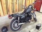
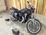
How it looked when I bought it:


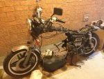
First time taking the engine out:


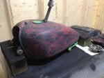
Repainting the tank (temporary):


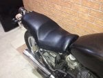
Redone seat cover (temporary):


The bike as it stood last year before any serious mods:

 
#720 ·
So the more I ride around on my bike, the more ideas I get to make it even better. One thing that I already wanted to do is clean up the wiring in the front, as well as make some better front turn signals.
However, I've been looking at redoing the controls too. One style that keeps catching my eye is the minimalistic approach. I love how simple it looks and also how clean it makes the bike look.
So for now I ride, but come this winter the plan is to do something similar to these handlebars:


#721 ·
So while I was out riding today I felt something give way in the throttle housing and there was a lot of play in the throttle suddenly.
I kind of figured I knew what it was though, the push cable on the throttle had been looking kind of worn and frayed when I cleaned the handlebar switches and I knew it was only a matter of time before it went:


Not a huge deal though as it's only purpose is to close the carbs if the spring return doesn't work and I knew my carbs springs were working well. Still though, there is a reason it's there, and even though it isn't needed for the bike to function properly, if the throttle should ever stick it is a good second defense against having a runaway bike. So for now I adjusted the cables and am currently only using the single throttle cable. The throttle feels much snappier that's for sure, but I will still be looking for a replacement cable, or if I can push myself a little more, I will purchase a set of murrays carbs which from what I understand are a single cable anyways.
 
#722 ·
So I finally received my brake lights (shipping from China takes a long time haha).


As I mentioned before, I will still be keeping the current brake light I have on the bike, these lights will just be a bit brighter and hopefully catch the eye of the person behind me better.
I was fooling around with ideas and I think I found one that will hopefully look alright on the bike and fit in with the sleek rear end. I am busy at school for the next few days, but hopefully I will mount them up later this week!

As you can see, they are drastically brighter than the LED light strip I currently have on the bike (to be fair, only the running light is on in the pictures though).

In bright sunlight:


Darker surroundings:

 
#724 ·
Thanks for the kind words Bill! Hopefully with the addition of these extra brake lights it will still look beautiful and also function just as beautifully. More than likely I will keep the flasher unit hooked up to the LED strip, and just have these brighter ones come on solid. We will see once I get a chance to mess around with the wiring again though :)
 
#725 ·
Well I seem to be running into a trend lately...having cables break while riding. This time the clutch cable decided to give out. Luckily I was stopped at a set of lights and in first gear, so the bike just stalled out and I was able to roll it off to the side of the road into a parking lot nearby. Then after going home, helping my dad get the trailer ready, and trailering the bike back home, I had to go and write two exams at school. Some days are just peachy aren't they!

All strapped down tightly:


Cable snapped at the handlebar end, probably due to the solder heating up the cable too much and making it more brittle:


So now I need to pickup a new cable. Since I put the clip-ons on though, the cable has been shortened, so the new cable will have to be slightly shorter than stock as well.
Does anyone have any good websites/companies/places to get a shorter cable for these bikes?
 
#726 · (Edited)
Well I seem to be running into a trend lately...having cables break while riding. This time the clutch cable decided to give out. Luckily I was stopped at a set of lights and in first gear, so the bike just stalled out and I was able to roll it off to the side of the road into a parking lot nearby. Then after going home, helping my dad get the trailer ready, and trailering the bike back home, I had to go and write two exams at school. Some days are just peachy aren't they!

All strapped down tightly:

View attachment 25393


Cable snapped at the handlebar end, probably due to the solder heating up the cable too much and making it more brittle:

View attachment 25394


So now I need to pickup a new cable. Since I put the clip-ons on though, the cable has been shortened, so the new cable will have to be slightly shorter than stock as well.
Does anyone have any good websites/companies/places to get a shorter cable for these bikes?
That's unfortunate and odd Micah. Sorry to hear. Check out:http://www.siriusconinc.com/search_...com/search_result.php?search=search&make=1&model=cx500&part=5&partno=&x=29&y=16
Either flat rate shipping or free shipping (can't recall) and they should have what you're looking for. They're also located in Cambridge and used by a few members here.
 
#728 ·
That's ironic! Guess great minds think alike. ;) How did it end up going with getting the cables sorted? Funny thing is, I still have a barely used choke cable as well as a throttle cables ordered from them a while back that wasn't needed after switching carbs over. Yeah, that tip in the photo wouldn't cut it. Hopefully, you were all sorted out to have your bike out during the weekend!
 
#729 ·
LOL very true! :p They were actually closed unfortunately. I guess the parts counter is only open Tuesday to Thursday, so I'll stop by there sometime this week when I get a chance.

I did have some time today to work on the bike though, and I thought to myself why couldn't I fix the cable I already have and use it as a spare.
So I went to the store and picked up a brass rod. Then drilled a hole, fed the cable through and bent the ends of the cable to keep it from sliding through:


Then soldered it in place:


and finally, cleaned it up:


After some adjustment it worked great! Went for a little ride around the neighborhood (staying within walking distance of course lol) and had no issues at all!
I will still pick up the new cable though and use that as a primary because I trust new cables better than old ones haha.


I also started wiring in the new brake lights, as well as decide what I am going to do with them.

I cut notches in the nuts so I can slide the wire through and tighten it up without disconnecting anything:


and the lights all wired up ready to be installed:


I will hold off installing them until the weekend, just so I can still ride the bike this week.
 
#734 ·
I can definitely sympathize with him lol. With these old bikes it's bound to happen at some point in time though I guess.
 
#735 ·
So most of you guys have probably seen or heard of Motogadget and the incredible products they make. Looking at their gauges and turn signals it's easy to see that German quality is not a myth. Unfortunately, along with the great designs comes great cost, something that makes me quite sad. I have been a fan of their bar end signals for the longest time, and absolutely love the m-blaze disc and the m-blaze cone.

Now comes the point where I am torn between buying them, or sourcing some cheaper alternative. Since I could not find any cheap units that I like, and I cannot afford to buy the m-blaze disc ($300+) I thought to myself....why not just make my own.

And so during class I started sketching some designs, making them as simple as possible while keeping the style of the motogadget unit:


After looking at my handlebars and taking some measurements, I made a 3D model in SolidWorks to give me a better Idea of what materials I'll need. Some of the dimensions are rough right now as I need to buy some different mirrors and measure them, scope out available materials, etc... but the general form of the turn signal is there:


You can see the exploded view along with details of the components that will need to be made/purchased in the list below:


1. Signal end - Machined on lathe, inside polished to mirror finish, outside black anodized/painted
2. Clear Lens - Cast out of clear acrylic resin with signal end embedded within
3. LED - 3W LED (same as rear turn signals)
4. Main housing - Machined on lathe, section for mounting clamp type mirror, M8 tapped threads, black anodized
5. Washer - M8
6. Rubber Tube - Used to hold the signal inside the handlebar tube
7. M8 Nut - Used to compress and expand the rubber filling the handlebar tube


So yeah, that's the plan. I am working on scoping out the materials right now, but from the looks of it so far, it will be a fraction of the cost of the Motogadget units.....plus it's going to be fun to make ;)
 
#736 ·
You will want a washer on both ends of the compressible rubber or the nut will just sink into it and not hold inside the bar.
 
#740 ·
Oh yeah, good point OCR. I just assumed the nut would push against the end, but didn't consider the fact that it might not be large enough. I will make sure to add the washer in. Thanks for the tip! :)
 
#737 ·
How do you tighten it once slid into the handlebar end?
 
#741 ·
It is basically the same setup as the motogadget one. You pre-tighten the nut so that the rubber fits snuggly into the handlebar, that way it won't spin around inside. Then all you have to do is turn the signal by hand and the nut will push against the rubber, causing it to expand outward and filling in the space. It might be required to adhere the nut and washer on the inside to the rubber, as they might spin freely and won't allow any tightening to take place, but we shall see when I get to that point.

This is from the m-blaze disc manual:
"Slightly tighten the M8 nut at the turn indicator to spread the rubber part. Maintain rubber-to-tube contact while inserting the turn indicator into the handlebar tube. Further spread the rubber part inside the handlebar tube by manually turning your turn indicator clockwise (do not use any tool!). Turn the turn indicator until considerable force has to be applied to keep it turning. When finished, the motogadget logo has to face upwards.
If the rubber part inside the handlebar does not spread: Pull out the turn indicator, bring the connector cable to its initial position by rotating the turn indicator counter-clockwise, increase pre-stress of the rubber by tightening the M8 nut and repeat the mounting process."
 
#738 ·
You also need power to the LED. Threaded tube?


R
 
#742 ·
Yes that is correct. You can't see it on the model, but there is a hole that runs down the center of the main section for the wires. While the part is in the lathe, I will bore out this center hole so that it is just large enough for the wires to pass through. I think I modeled it as 1/8" at the moment.
 
#739 ·
I am a fan of Moto-Gadget to - I have the M-Lock incorporated into my set up. However, I found the end of the bar indicators at Dime City Cycles.
Here's a shot of them - they work well and apart from being a pain to route the wire (wire goes inside the bars), weren't bad for installing.


Good luck

John
 
#743 ·
I am a fan of Moto-Gadget to - I have the M-Lock incorporated into my set up. However, I found the end of the bar indicators at Dime City Cycles.
Here's a shot of them - they work well and apart from being a pain to route the wire (wire goes inside the bars), weren't bad for installing.
View attachment 25748

Good luck

John
Yeah they make some gorgeous products! I would love to purchase a lot of them, but funding is pretty tight right now with school and all. Some day though haha.

Those bar end mirrors are similar to the ones I've seen from other sites as well. They look pretty slick for sure! Definitely makes me want to build these all the more now!
Since I've put the clip-ons on, there is an opening at both ends for the wiring to go through, so no drilling or cutting necessary. This winter I hope to simplify the controls and have the wiring go through the tube for a nice clean look. I have a little over 1/2" ID so there should be enough room for all the wires hopefully.
 
#748 ·
So last night I was also able to get to my brake light and modify it to make it brighter.

After looking at the rear of the bike for some time, and trying to figure out how I could mount the lights, I kept coming to the same conclusion; the rear looks really good as it is.
And so with that in mind, I decided that I didn't want to change the look of the bike, but at the same time I still needed to make it brighter. So that's when the I started to tear down the tail light and see what was inside of it to work with.
I decided what I would do is trim the outermost LED's and replace them with my high power ones, thusly keeping the same style but improving the performance of the light drastically.

First step was to take apart the casing of the LED's so that I could mount them inside the housing:


These suckers get pretty hot if left on for a while, so I made sure to coat the ends with high heat silicon in order to dissipate the heat a bit and also keep the LED's more rigid. Not the prettest, but they get covered up afterwards anyways:


Now to mount the LED's into the housing. The last two LED's on either side of the current brake light had to be removed in order for the new lights to fit in:


Then it was just a matter of drilling the holes for the new lights, and also rewiring the contacts on the previous light to get a closed loop again:


Then some more high heat silicon to hold the LED's in the housing. It's good because it will also absorb some of the vibration too:


And lastly to reattach the red lens on the light. As you can see below, there are enough of the original LED's to still have a good running light:


And after testing it for a bit I am very pleased with how it turned out. To the naked eye, the light looks almost the exact same and the rear of the bike still looks great I think. But as soon as the brake is applied the differences start to show. Much brighter and should definitely be seen in daylight now. I still have all the LED's wired up the flasher module so the lights flash for about 3 seconds before staying solid when the brake is applied which also helps grab peoples attention.
Pictures don't really do it justice, but you can kind of see the before and after in the pictures below. Before is on the left:


So next step is to start fabricating those bar end signals. I won't have access to a shop for a couple weeks, but I am working on purchasing all the materials at the moment.
 
#749 ·
I modified the 3D model of the turn signal a bit and started working on the detail drawings so I can make them up easily.
I shortened the length of the acrylic as it stuck out too far before, also changed the nut to a flanged lock nut like Randall and OCR mentioned, and modified the section for the mirrors to clip onto:


Now, originally I was only going to have a single LED on each signal that would illuminate 360°, but I got to thinking, if I had two and placed them so that one would be further forward, and the other at the rear, the signal will light up a bit brighter from the front and rear rather than all around equally. The light will still shine in all directions hopefully, but a bit more will be directed towards the areas of interest.


Let me know what you guys think would be the best option!
 
#750 ·
A triangle configuration would be even better as you could then have two at the front making the signal even more visible.
 
#751 ·
Very true! I wonder if it might be too bright then though? Those LED's really shine bright at 3 Watts each. Maybe I can find some smaller 1 Watt LED's and use the triangle configuration then. I will begin my search...
 
#752 ·
Another option that might work if I just use two LED's is cutting out a flatter section in the reflective portion that angles towards the front. This way, more light will be directed to the front while still allowing light to pass all the way around.
I would turn the piece on a lathe, then cut out the groove using an end mill.


  • Like
Reactions: OCR
#753 ·
So I was able to get access to a lathe and mill for a few hours today. A friend of mine was kind enough to let me use his equipment and I was able to make a bit of progress with the turn signals.
I forgot that machining takes a lot longer than you think though lol (not to mention it was my first time using a lathe), so I was only able to get one piece made....but I am quite proud of it :D

I was able to grab some 1-1/2" aluminum round stock and then set to work making the signals:


After some test passes and learning the machine a bit I started machining:


I first made the threaded section to avoid the possibility of it shearing off:


Then drilled part of the center hole for the wires to pass through:


Next up was to machine the section for the clamp-on mirrors to go. This section is a bit longer than the mirrors and the diameter is just smaller than the ID of the handlebars so it should slip right in and help support the mirrors and signals a bit:


Then flipped the piece around and machined the top portion as well as drilled the rest of the hole for the wires:


I forgot to take pictures, but I threw the piece in the mill and cut the groove in the top for the LED's to fit in. And BAM, we have the makings of some turn signals! I think this piece turned out really good and very pleased with my first part ever turned on a lathe:


Next time I can get access to the shop I will make the other side and hopefully start on the end pieces!
 
#755 ·
I'll put you at the top of the list, but I think I'll have to make sure I can machine another one before taking orders :p
 
#756 · (Edited)
So after two failures (was rushing too much) I was able to make the second main section. Now I have a nice matching pair:


Then it was time to do some polishing. I used progressively finer sandpaper and then the dremel with a polishing wheel and compound to get a nice reflective surface on the ends to increase the dispersion of the LED lights. Only the left one was done in the picture:


I also picked up the resin as it was on sale at the craft store. I got the larger volume one so I can do some tests as I've never worked with the stuff before.


I have exams coming up soon though unfortunately, so I don't know when I will be able to machine the last two components for the turn signals, but I will try to get to them as soon as possible!
 
  • Like
Reactions: LazerHead
#757 ·
I was able to source some rubber tubing which will hopefully work well. The ID is a bit larger than the threaded shaft so I might need to have a little spacer in there so that it doesn't twist inside the handlebar:


And I also got my LED's in today. So after tearing them apart I ended up with this:


Now the sad part though. You can see on the far right that the negative lead snapped off at the base while I was removing the LED's from their casings. And while I was re-wiring the LED's to fit inside the main housing, I broke another one off <_<
For some stupid reason I forgot to buy a few extra just in case I messed up, so now I have to wait until the new ones come in. Just another set back as usual...